
Work · NASA MINDS Lunar Mission Challenge · Artemis Ionic Thruster · RSCL
Electrohydrodynamic Thruster Demonstrator
A solid-state propulsion demonstrator with no moving parts, producing thrust by accelerating ions through a high-voltage field instead of burning propellant.
The problem
Chemical propulsion carries its fuel, and every kilogram of it is a kilogram of payload not carried. Electrohydrodynamic thrust removes the propellant entirely, at the cost of needing kilovolts across a millimeter-scale gap without arcing.
The supply that produces those kilovolts also has to be light enough to fly, which is precisely where this class of design usually fails.
What I did
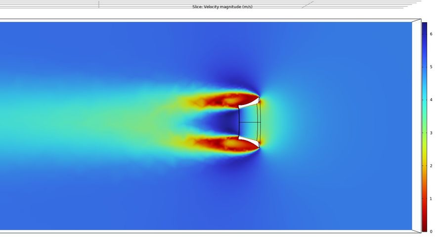
A multi-stage collector–emitter configuration was sized against computational flow modeling before it was built, with the geometry chosen to maximize ion acceleration across the stages rather than a single gap.
Electrode surfaces were electroplated to improve ionization and to survive sustained high-voltage operation, which is a durability problem as much as an efficiency one.
Power came from a MOSFET-amplified high-voltage architecture. The emitter-to-collector gap was swept at 30, 25 and 20 mm and the resulting airflow measured directly with an anemometer at each spacing.
Result
The thruster produced sustained, consistent airflow throughout operation — the physics worked and held.
The limiter was the power supply, not the thruster. A prefabricated high-voltage transformer had been chosen to keep the demonstrator light; it dropped voltage badly, capped usable input at 4 V, and held peak airflow to 1.3 m/s.
That makes the finding a clean one: the collector–emitter design was not the constraint, and a custom transformer designed for this load is the next thing that has to be built. Reporting the ceiling and its cause is more useful than reporting the number alone.
From the report
Bench photographs and measured data from the project's own report.